In Fall 2023 I took 6.2050 (Digital Systems Laboratory). Here we learned about digital logic, FPGAs, System Verilog, communication protocols, and more. Weekly assignments included:
- Implementing an SPI transmitter and receiver
- Drawing shapes over HDMI
- Decoding audio
A large part of the class was a final project which I worked on with Andi Qu. At the beginning of the final project period Joe Steinmeyer, the lecturer, showed some previous examples, which all set the bar high:
- Using stepper motors to play songs
- A internet controlled laser projector
- A robot that plays airhockey
After brainstorming for a while we decided to focus on what FPGAs can do better than regular computers: real-time processing. We decided to build a robot that could recognize it's owners voice, localize them in a room, and move towards them. Effectively a robotic cat or Feline Programmable Gate Array.
To save the suspense here's the final result. The demo video isn't the best but you can see, especially towards the end, that the robot moves towards me.
Our design goals
We wanted to built a robotic cat that moves towards it's owners voice. We split this into different sub-goals:
- I2S audio input (Richard)
- MFCC feature extraction (Andi)
- Bluetooth communication (Andi)
- Real-time SVM inference (Andi)
- Motor control (Richard)
- Real-time audio localization (Richard)
These would all fit together like:
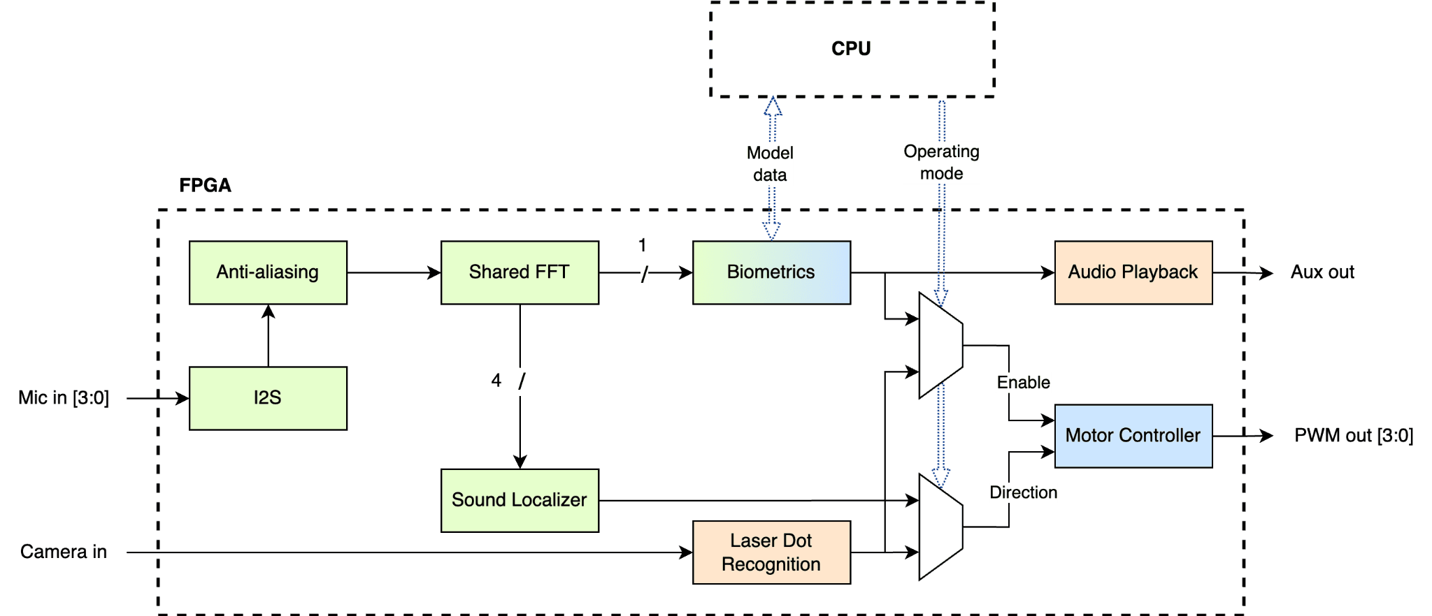 System overview diagram
My contributions
For full details you can read our report or see the code but here's a brief overview of my contributions.
Audio input
The first step of being able to recognize a voice is to get the audio. We used the SPH0645LM4H-BI2S MEMS microphones on Adafruit breakout boards. To be able to perform localization we needed four of these arranged in a triangle on a breadboard with one central microphone. The idea for localization was that there would be a phase difference between when each microphone sampled the audio signal.
These microphones use the I2S protocol for transmitting audio data. In the standard I2S protocol data is written on the falling edge of the serial clock (SCK) as shown below
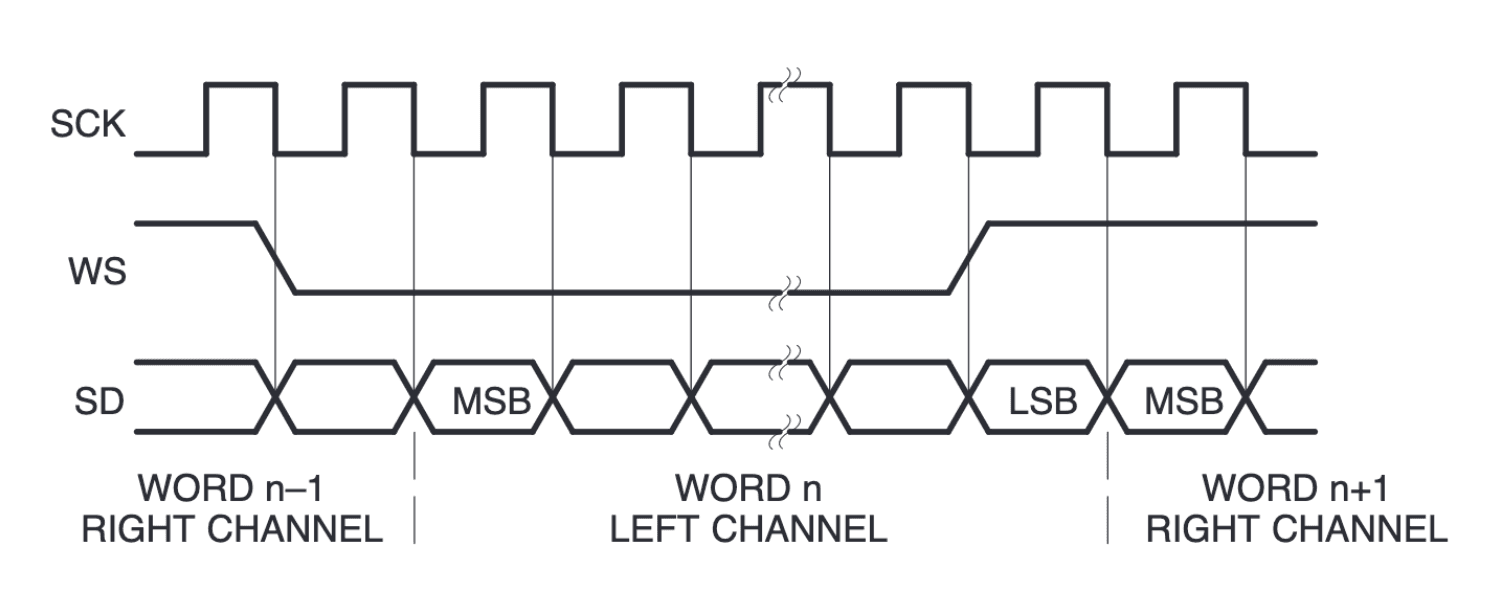 Standard I2S timing diagram. DATA changes on the falling edge of the clock
However, the SPH0645LM4H-B writes data on the rising edge of the clock.
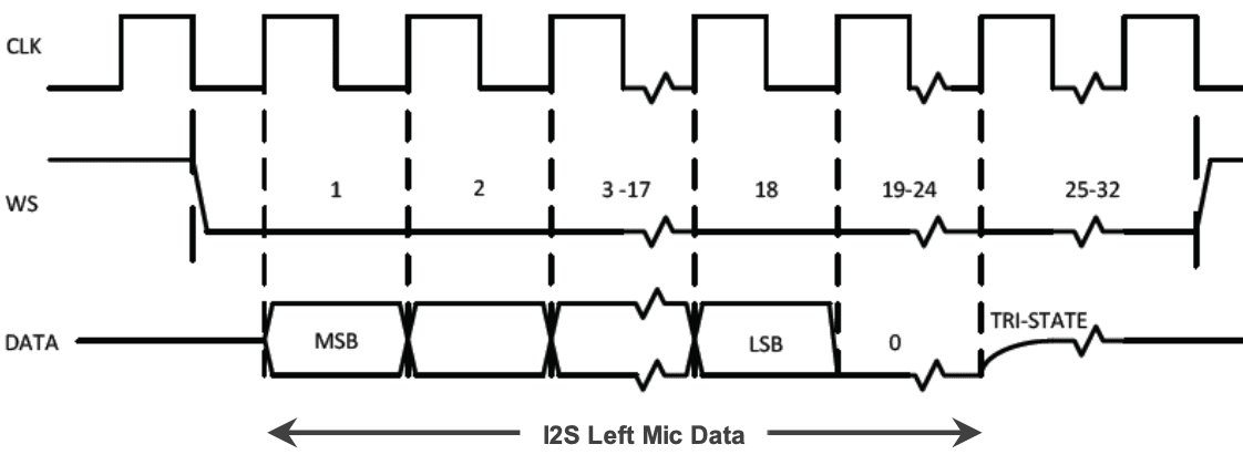 SPH0645LM4H-B timing diagram. DATA changes on the rising edge of the clock.
This meant I had to write a custom I2S controller and reciever to handle this. The I2S controller generates the serial clock (SCK) and word select (WS) signals and the I2S reciever reads the data from the microphones.
I spent about three weeks trying to get these microphones to work, even after spending hours with the TAs and Joe I couldn't figure out why the audio was so quiet. Then one day while looking at the data with an oscilloscope I noticed that six most significant bits were always 1 during testing. I left-shifted the audio by six bits and the audio was much louder and easier to work with.
Filtering and decimating the audio data
Human speech typically occurs from between 20 Hz to 3 kHz however we sampled at 32 kHz so it I passed the audio through a low-pass finite impulse response (FIR) filter. I used the Xilinx FIR Compiler IP which also supports decimation so I could reduce the sample rate to 8 kHz.
Getting the phase and amplitude data
Both the localization and voice biometrics required the phase and amplitude of the audio signal. I used the Xilinx FFT LogiCORE™ IP block configured with four channels (one for each microphone) to operate on 512 samples which we experimentally determined to strike a balance between resource usage and accuracy.
Sound localization
The idea behind sound localization is that the phase difference between when each microphone samples the audio signal can be used to determine the direction of the sound source.
First I took the 512 calculated FFT coefficients and discarded the upper 256. By the Nyquist-Shannon sampling theorem only the lower 256 were usable. Then I convert all the coefficents from rectangular form to polar form.
Then for each frequnecy I did the following process
- Calculate the phase difference between the central microphone and the other microphones
- Scale each of the peripheral microphones by the phase difference and the amplitude at the central microphone
- Sum the scaled locations
- Assign the resulting direction vector to one of 16 bins
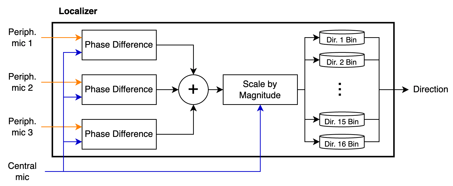 Strucutre of localization module
Once all the 256 frequencies have been processed the bin with the greatest magnitude is the direction of the sound source.
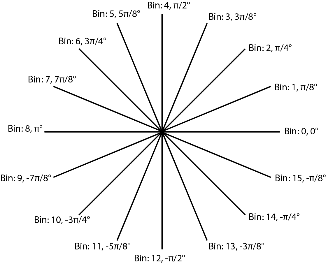 16 angle bins and their corresponding angles
Motor control
Servo Motor Contro
To test sound localization I generated PWM signals to control a serve motor. I mapped each bin to a different duty cycle and the servo would move to that angle.
DC Motor Control
Initally, I tried to use continuous servos to move the robot. However, these motors generated enough noise to interfere with the localization module. Instead, two Adafruit DC Gearbox TT Motors were used, these have three ports: IN1, IN2, and EN. IN1 and IN2 control the direction of the motor and were always set to low and high respectively, as the motors only moved clockwise. EN controlled whether the motor is enabled. I generated a PWM signal for the EN pin to vary the motor speed. I choose 20 kHz to not interfere with localization or voice biometrics.
