
In Spring 2024, I took 6.115 (Microcomputer Project Laboratory) at MIT. It takes a deep dive into embedded systems. Over four labs we built circuits and wrote code to
- Find the resonant frequency of an fluroscent light and strike it
- Display a laser light show
- Control a robot arm
- Reconstruct a 3D object from 2D images
All of which was done on a 8-bit Intel 8051 microcontroller which we programmed in assembly.
For the last month of the class we had a final project. The only critera is that it has to use the Cypress PSoC 5LP.
I decided to build a robot that could play Connect 4 on a physical board for a few reasons
- I love building things that interact with the physical world
- I wanted to explore the algorithms behind a game-playing AI
- Most importantly, I suck at Connect 4 and wanted to build a robot that could beat my friends in my place
Below I describe the design and implementation of the robot but if you want to see it in action, here's two videos:
Design Goals
The robot had to meet the following requirements:
- Play Connect 4: The robot should be able to play Connect 4 on a physical board
- Simple mechanical design: The robot should be easy to build and maintain
- Fast: The robot should be able to play a game in a reasonable amount of time
Mechanical Design
At the start, I was most unsure about how the actuate the robot. I considered a few options:
- I could have seven different hoppers – one above each column:
- But this would require seven servos and was IMO excessive.
- One hopper attached to a timing belt so it could be positioned with a stepper?
- With stepper motors, I'd have to home it and then keep track of its position.
Eventually, I settled on a design with a fixed hopper and a plane mounted to a servo that would cover all columns up to the one I wanted to place a game piece in:
With this decided, I created a CAD model of the robot in Fusion 360. I made the thickness of all the extruded pieces parametric so I could easily adjust them before laser cutting and used finger-joints to allow for easy assembly.
The Gotchas
It took a few iterations to get the design right. Here are some of the issues I ran into:
-
Aryclic vs Plywood: Initally I wanted to use acrylic but it was too brittle and would crack when I tried attach the pieces. I switched to plywood which was much easier to work with.
-
Ensuring pieces fell into the right place: I had to experiment with the angle of the plane so the pieces would roll but not so fast that they'd miss the column they were supposed to go in. Additionally, I added a lip after each hole in the plane to stop the pieces from rolling further.
-
Game pieces would get stuck on plane: I had to add tape to the front and back plane to reduce friction. Additionally, I made the plane out of aryclic so that it was more slippery.
All in all, I went through 5 iterations of the design before I was happy with it.
Electrical Design
Detecting Game Pieces
I used seven RPR-220 reflective photosensors to detect when a game piece had fallen into a column. These are a single package with an LED and phototransistor. I placed them at the top of each column. I used copper-tape to ground both ground legs and connected the signal legs to the PSoC.
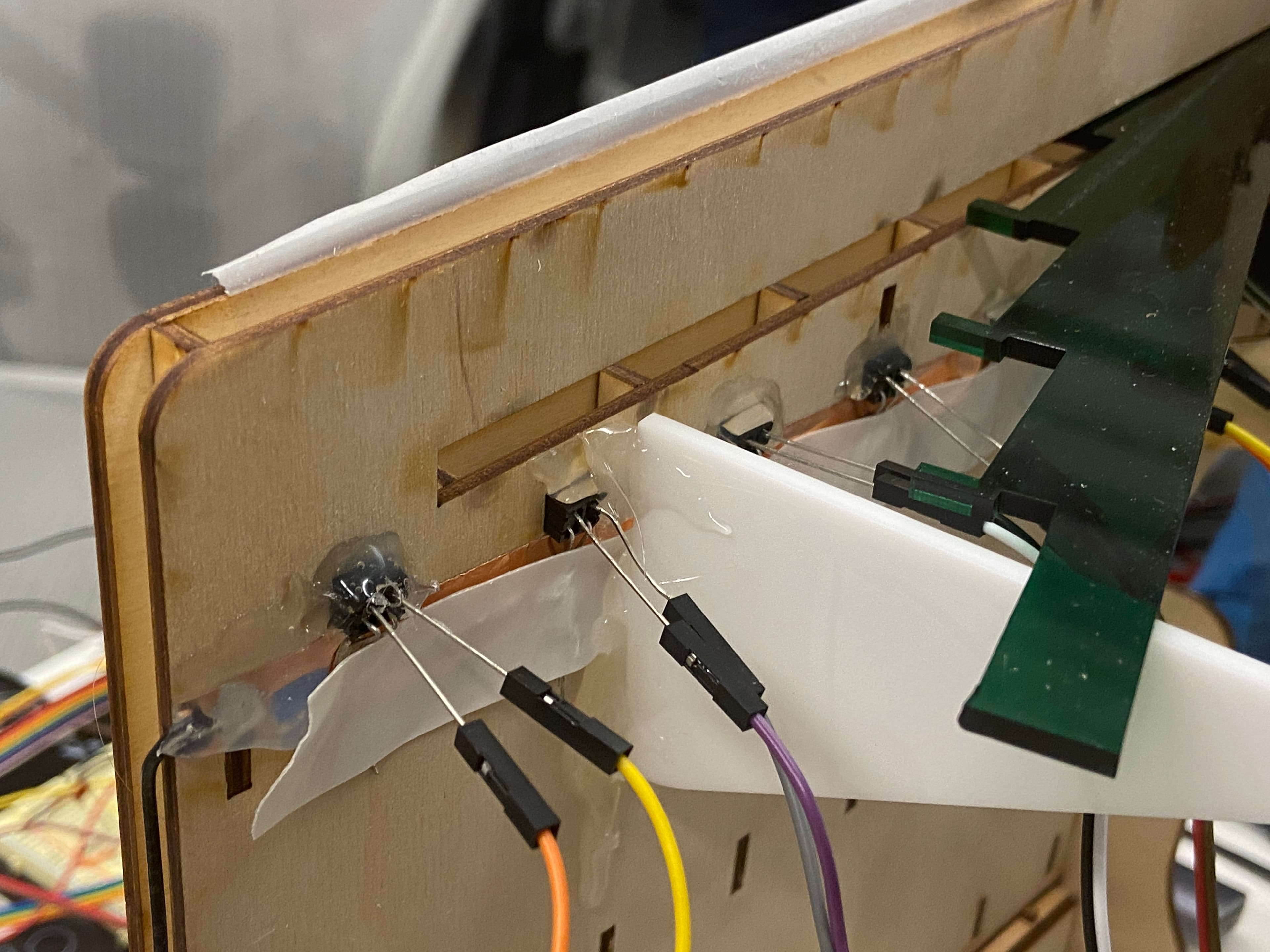 Photointerrupters on back of robot with copper tape
The current through the phototransistor varies with the amount of light reflected back. The datasheet specifies that at 6mm the current is 100% and it drops off when a piece falls in front. Therefore I used a pull-up resistor such that when a piece falls down the current drops and the voltage goes high. Since I used red and yellow game pieces the current never went to 0% so I adjusted my resistor value until the PSoC read a high voltage when a piece was in front of the sensor (around 1.25V).
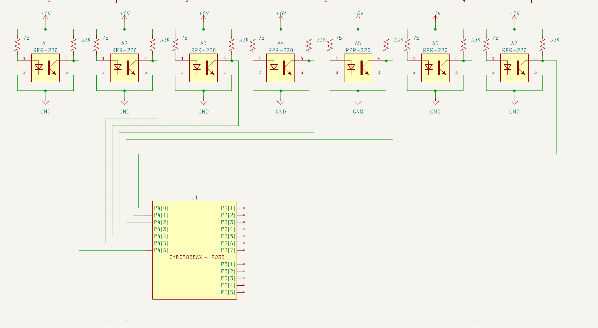 Schematic of photointerrupters and PSoC 5LP
Displaying the Game Board
I used a HiLetgo ILI9341 TFT Screen. It is a 2.8" touch screen with an SD card reader. Additionally, PSoC supports the emWin library which makes it relatively easy to draw shapes and text on the screen.
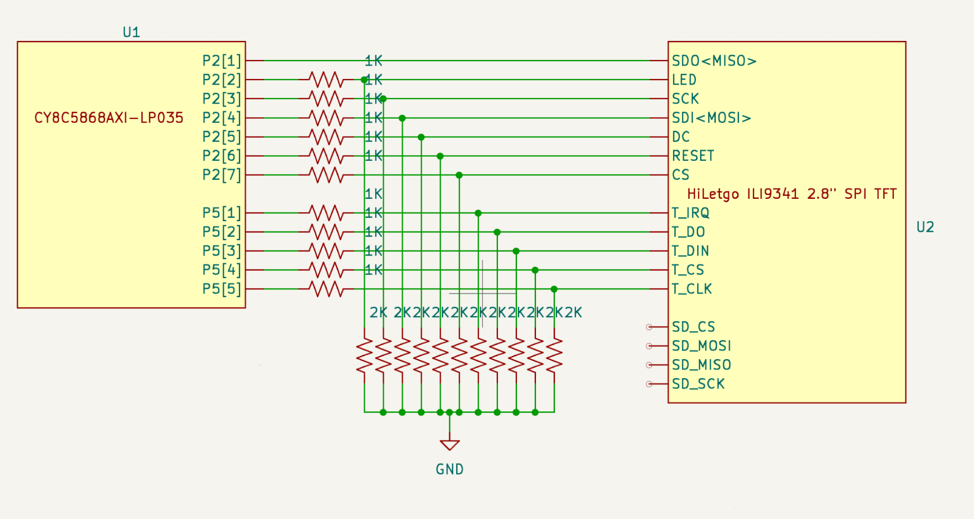 Schematic of TFT Screen
Playing sound effects
I used a 8-ohm speaker along with a LM386 amplifier to play sound effects. As I only wanted to play tones I didn't need to implement any filters.
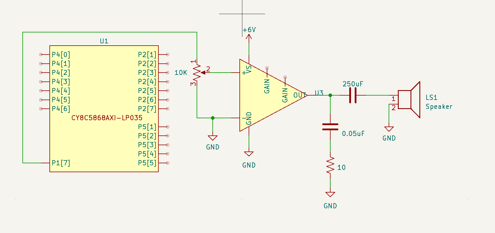 Speaker schematic
Actuating the robot
Finally to actuate the robot I used two servos. One to move the plane and the other to drop the game pieces.
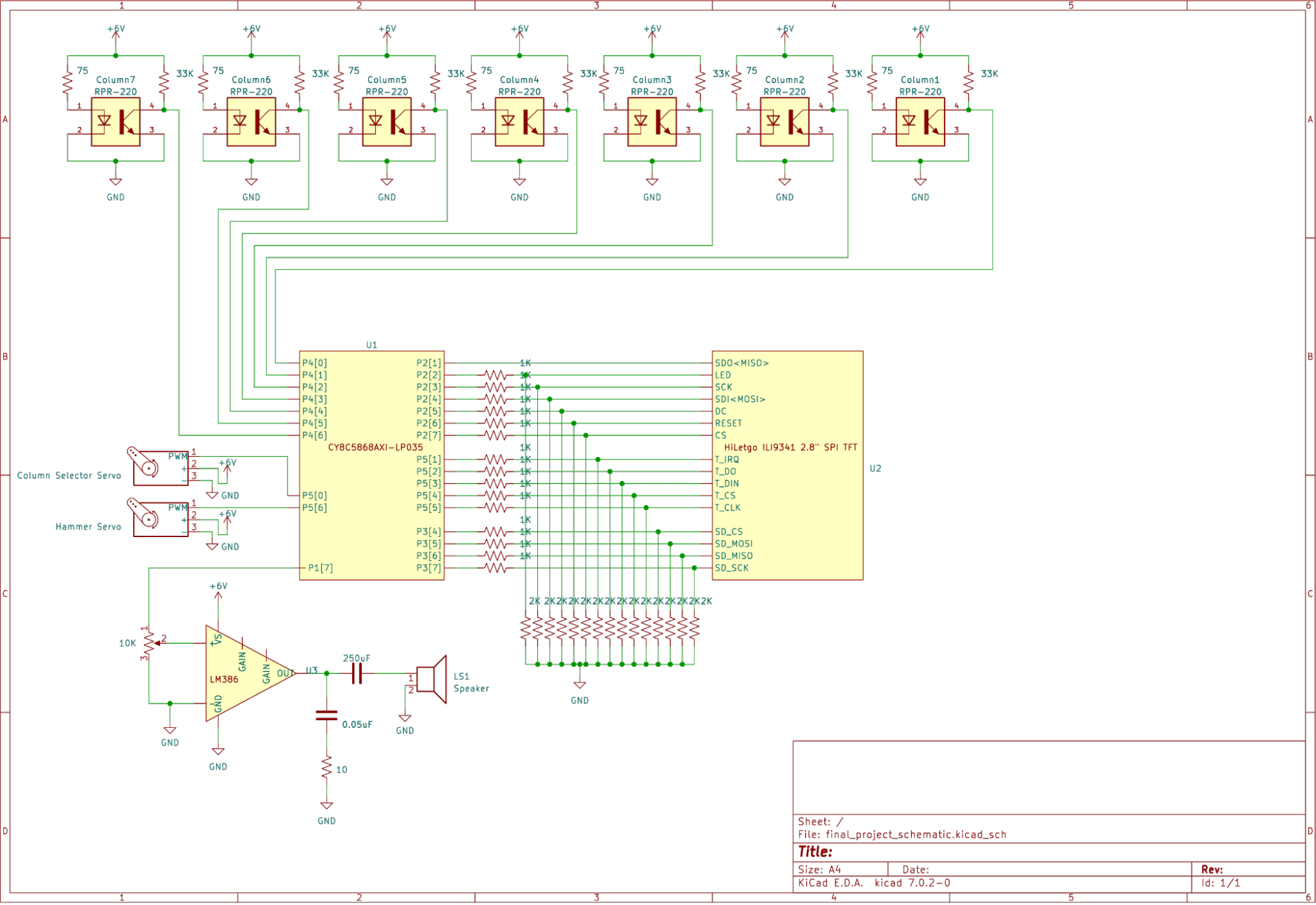 Full robot schematic
Software Design
My high level software design was:
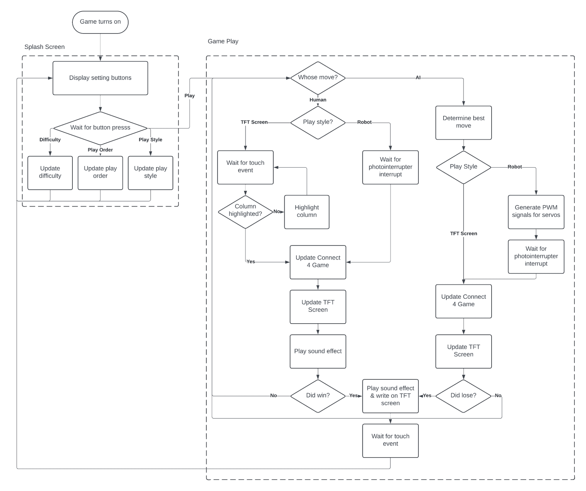 Software flowchart
The full code can be seen on Github
All the code was written in C. I tried dividing the code into modules to make it easier to debug and test. Here are the modules I used:
TFT Screen
I used the emWin library to draw the game board and game pieces on the screen. I also display a settings screen where the user can select: the difficulty level, who goes first, and whether they want to play on the robot or the screen.
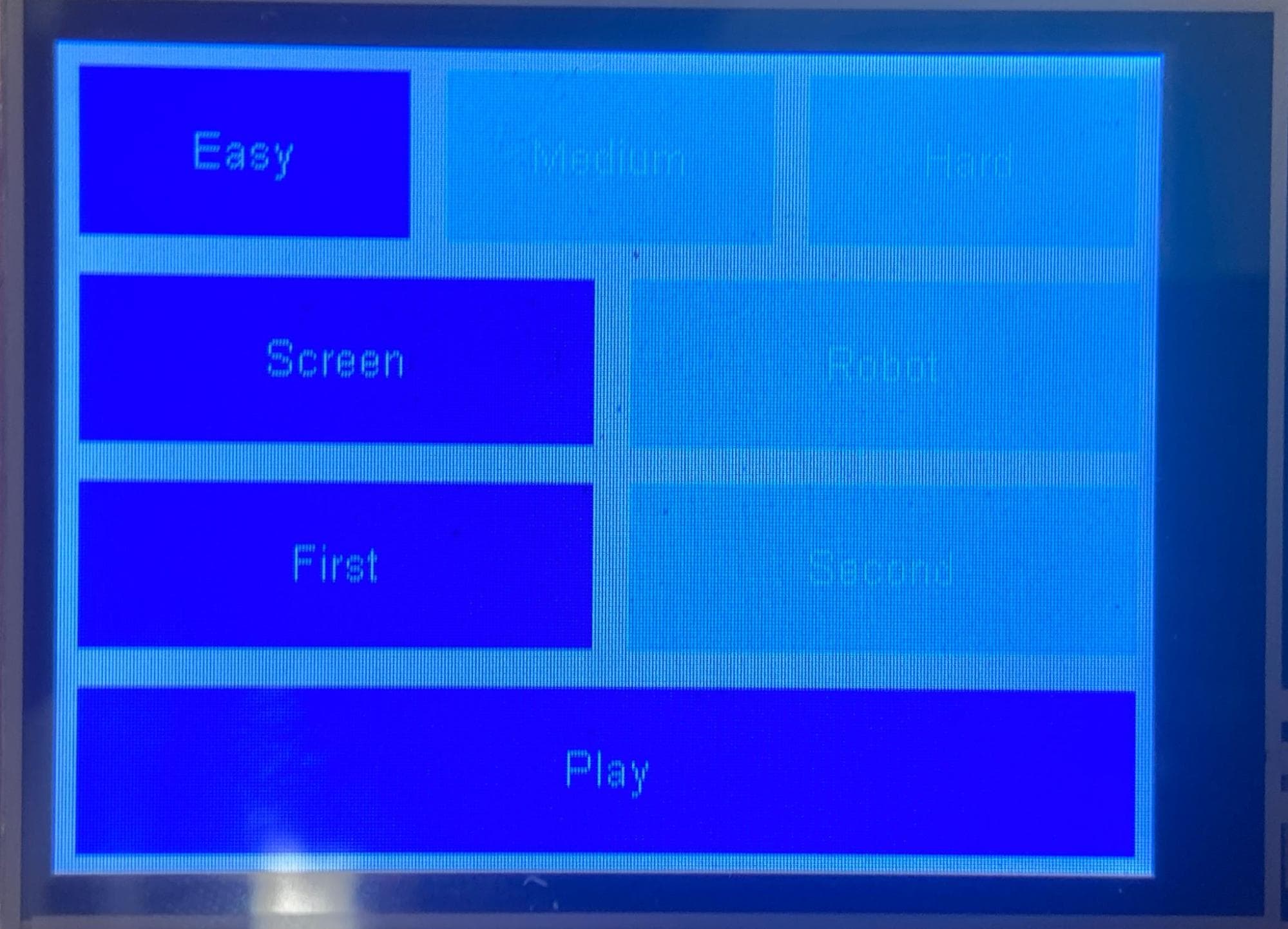 Settings displayed on TFT Screen
There are two modes: screen play and robot play. In screen play the user uses the touchscreen to select which column to drop a piece in. During both modes the robot displays taunts to the user. I used the emFile library to read taunts from a text file on a SD card.
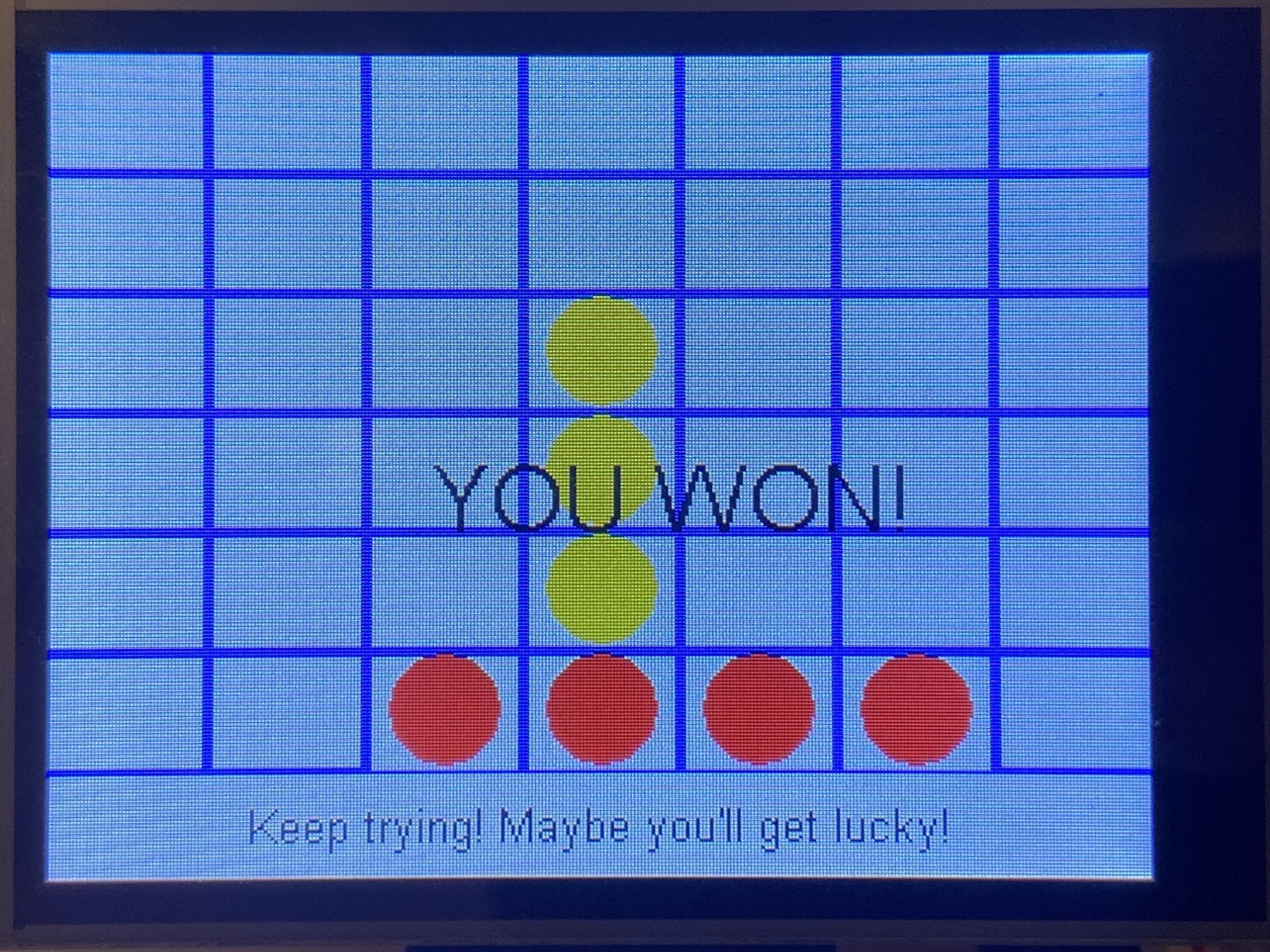 A game of Connect-4 on the TFT screen
Connect4 Game and AI
I implemented Connect4 using a bitboard representation as described here. For each player I stored a 64-bit number where a 1 represented their game piece and a 0 represented an empty space or the other player's piece.
The benefit of this representation is that I can efficently check for wins by using bitwise operations.
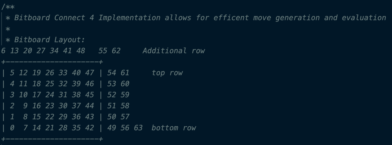 Connect-4 bitboard representation
I implemented the AI using a minimax algorithm. The idea is that the AI has a heuristic function that evaluates a given board state. I then simulate all possible moves up to a certain depth and choose the move that maximizes the heuristic for the AI and minimizes it for the player.
I allowed the user to choose three difficulty levels:
- Easy: The AI only looks one move ahead
- Medium: The AI looks five moves ahead
- Hard: The AI looks 10 moves ahead
However, at 10 moves ahead the AI would need to evaluate 7^10 = 282,475,249 moves which was too slow. Therefore, I implemented two optimizations:
- Negamax: I simplified the minimax algorithm by using the zero-sum property of the game. The AI player's score is the negative of the human player's score. Therefore, I only need to implement the max part of the algorithm.
- Alpha-Beta Pruning: I used alpha-beta pruning to reduce the number of nodes I needed to evaluate. The idea is that I maintain two values, alpha (the best guaranteed score for the maximizer) and beta (the best guaranteed score for the minimizer). I can then prune all nodes that are less than alpha or greater than beta.
For the heuristic function, I gave each position a value for example the lowest row on the center column is the best position to play in. Then I calculate the score for each player by summing the values of their pieces and add extra points if they have three-in-a-row.
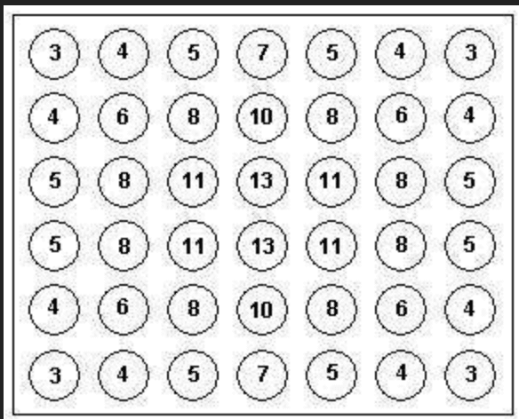 Values given to Connect-4 positions
Controlling the robot
First, to detect the pieces I had an interrupt triggered by the photointerrupters. I had to debounce the signal as the controller was fast enough to detect the piece multiple times as it fell.
Then, I manually found the right PWM values to move the plane and drop the pieces. I had to account for the slight wiggle of the servo.
Occassionally, the piece would fall into the wrong column. I had the robot always detect where it's piece actually fell and roll with it if it was in the wrong column. This isn't a real fix but I think it adds some randomness which makes the game more fun since you can occassionally actually win.
PSOC Hardware
One of the major draws to the PSoC is it's programmable hardware. The PSoC comes with a bunch of blocks you can instantiate and connect to each other to make DACs, ADCs, PWMs, etc. I used the following blocks:
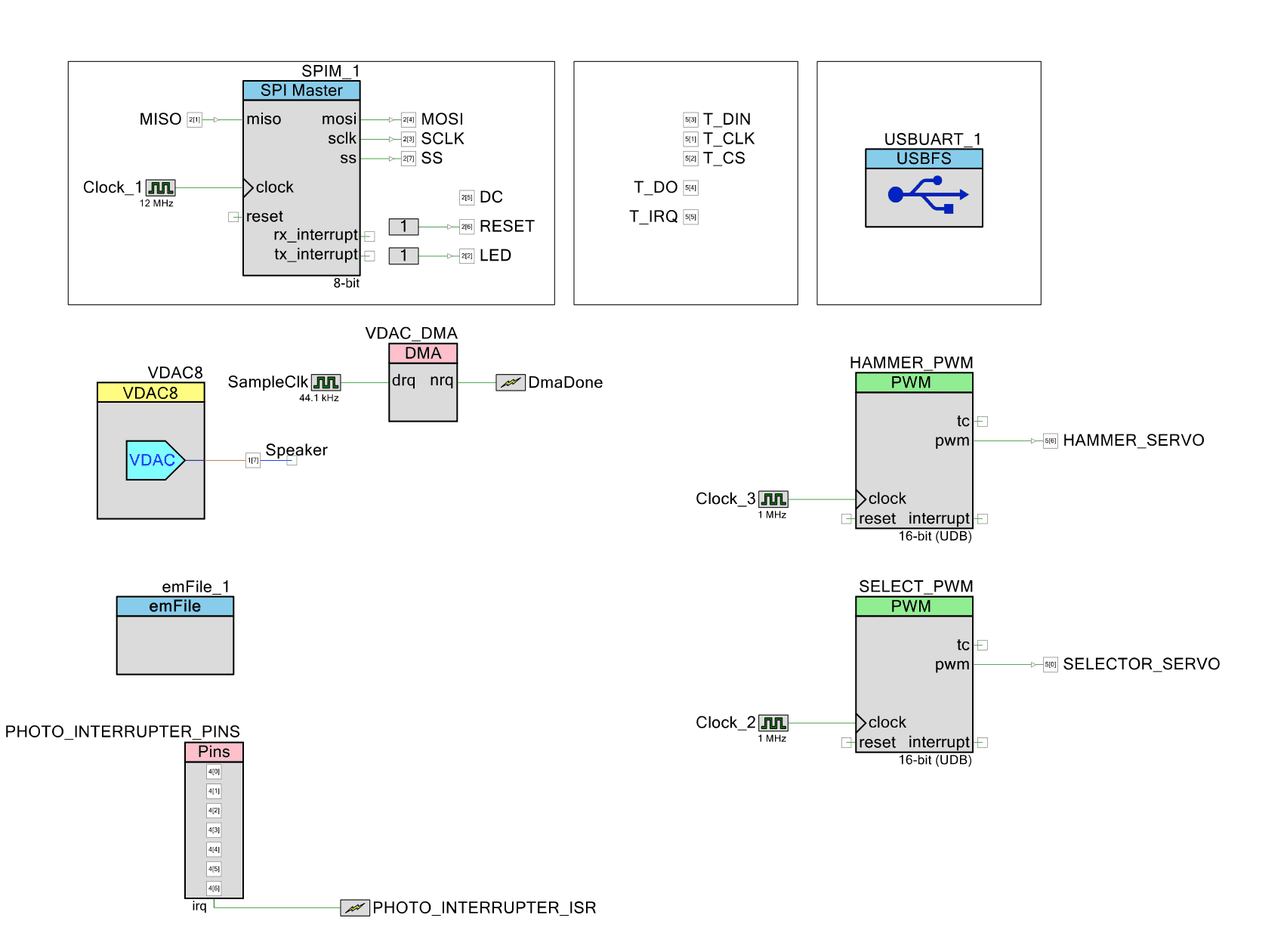 PSoC Hardware
- SPI: To communicate with the TFT screen
- Digital Pins: To communicate with the TFT touchscreen module
- PWM: To control the servos
- USBUART: To send debug information to my computer
- emFile: To read files from the SD card
- Digital Pins + Interrupt: To read the photointerrupters
- VDAC and DMA: To play sound effects
Conclusion
My Connect-4 Robot was a fun project to build. I learned a lot about embedded systems, game playing AI, and mechanical design. I also got to play a lot of Connect-4 but I can't say I got any better at it. There was a lot of work in designing, building, and debugging the robot but it was all worth it to see it in action. Above is only a high-level overview of the project. If you're interested in more details, feel free to reach out to me or look through the code.