As a kid I loved my Arduino Uno and I always wanted to make my own. After learning Eagle and how to mill PCBs I decided to make a dev board for the SAMD21E microcontroller. This board includes a microusb, barrel jack, reset button, and status LEDs.
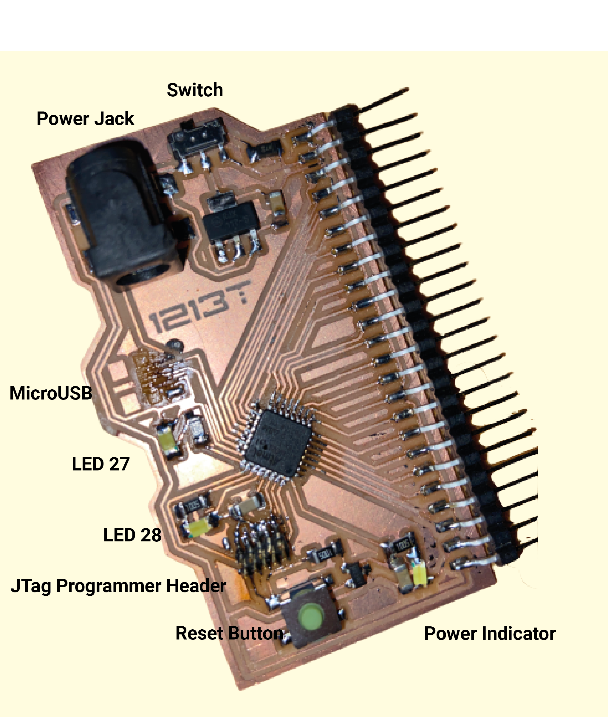 Labelled Dev Board
Designing a dev board
To build mine I decided to approach it in spirals. First I implemented everything in Prof. Neil Gershenfeld HTMAA example schematic for a SAMD21E board.
Breaking out the pins
Afterwards, I started adding in the extras. First, I wanted to break out all the pins so I could use them with future breakout boards. I opted to use horizontal pins instead of vertical ones so that if I put the board in my pocket it wouldn't stab me as I walk around. I broke out all the pins on the SAMD21E which weren't already being used except for 4:
- PA00 and PA01 are both special oscillator pins designed to be used with a crystal. As I didn't need to do this I ignore them
- I kept PA27 and PA28 to have as one board status LEDs
Then I connected them to my FTDI headers. As there were more header pins than SAMD21E pins I also included ground and 5v / 3.3v pins in some places. My first ordering ended up not being the best but I switched stuff around in the routing stage to make everything work great.
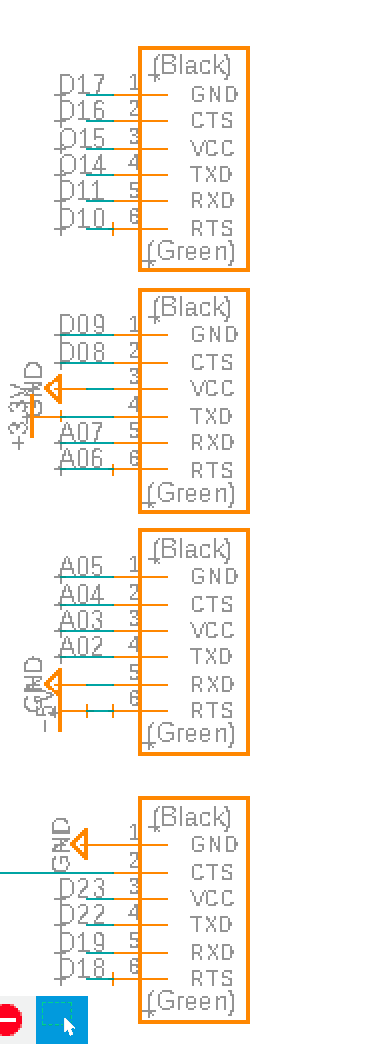 Header schematic
Adding a reset button
When working with Arduino code sometimes things go wrong, you end up in a weird state, or you just need to run everything from the start again. Most Arduino boards contain a reset button which takes care of restarting the microcontroller. I wanted one for my dev board also.
The reset pin works by restarting the microcontroller if it's ever brought to ground. It's already being used by the JTag so I connected my extra extra components to the same net. First, I wired the pin to a 100ohm and then to 3.3v. Then I included a button which when pressed will short the whole line to ground.
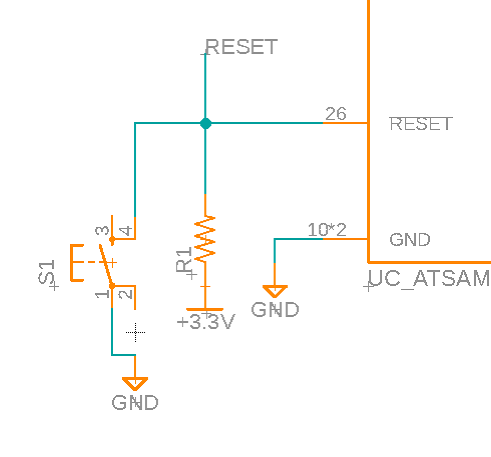 Button schematic
Power and Status LEDS
When the microcontroller has power I want an LED to always come on. Then I wanted two other LEDs just for random debugging and as status indicators. For the power LED I wired it directly to 3.3v and ground
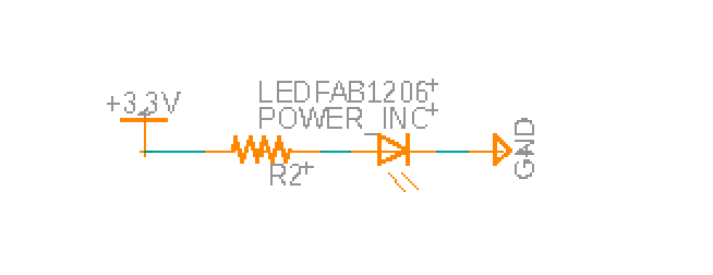 Power led schematic
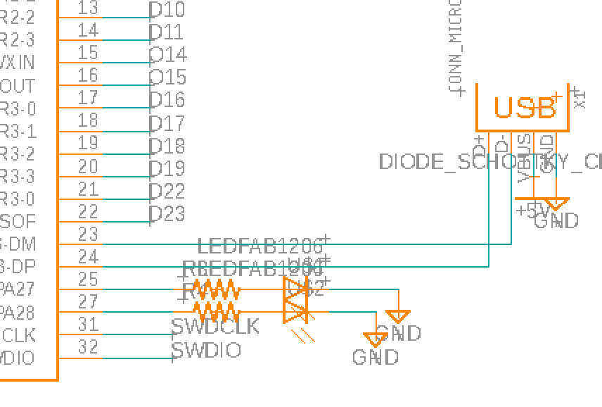
For the status indicators, I wired resistors to PA27 and PA28 which connect to LEDs.
Microusb
Of course I wanted to be able to program my board so I included a microusb.
 Microusb schematic
Barrel Jack Connector
I'm not always going to have my computer around to power the board so I wanted to be able to power it off a barrel jack connector. As this would have 12V I needed to also add a 5V voltage regulator (which connects to the same 5V line as the microusb).
I connected a switch to the barrel jack. When on the switch sends the 5V from the regulator to the board and to a pin. When off the 5V only goes to a pin.
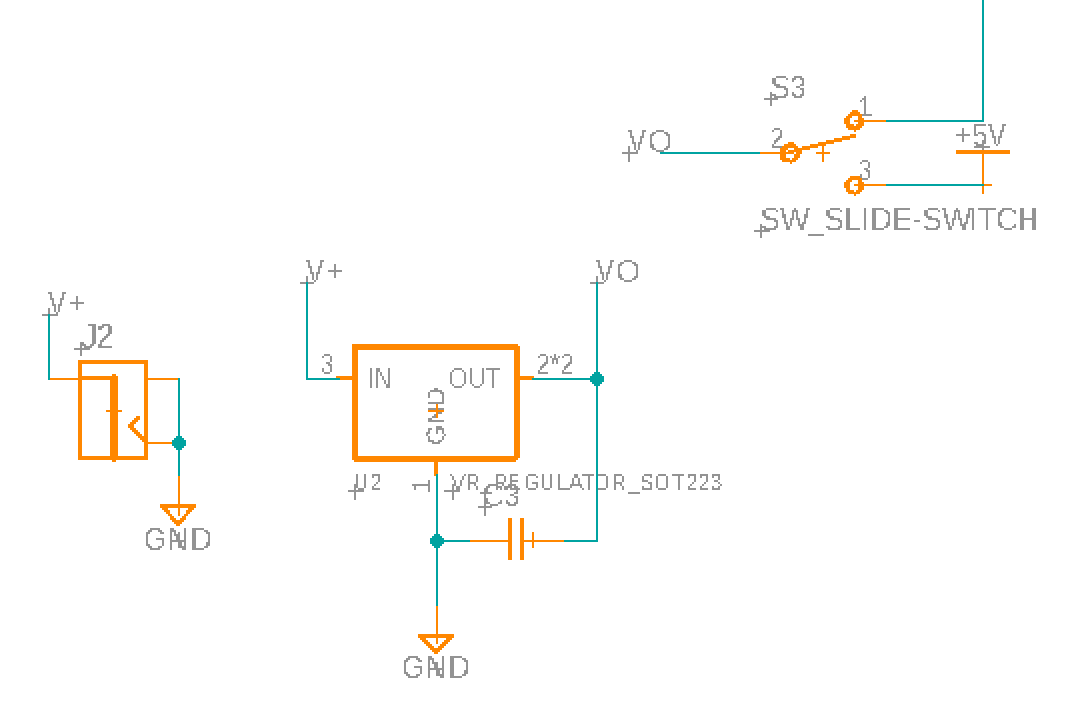 Barrel Jack Schematic
Schematic for the dev board
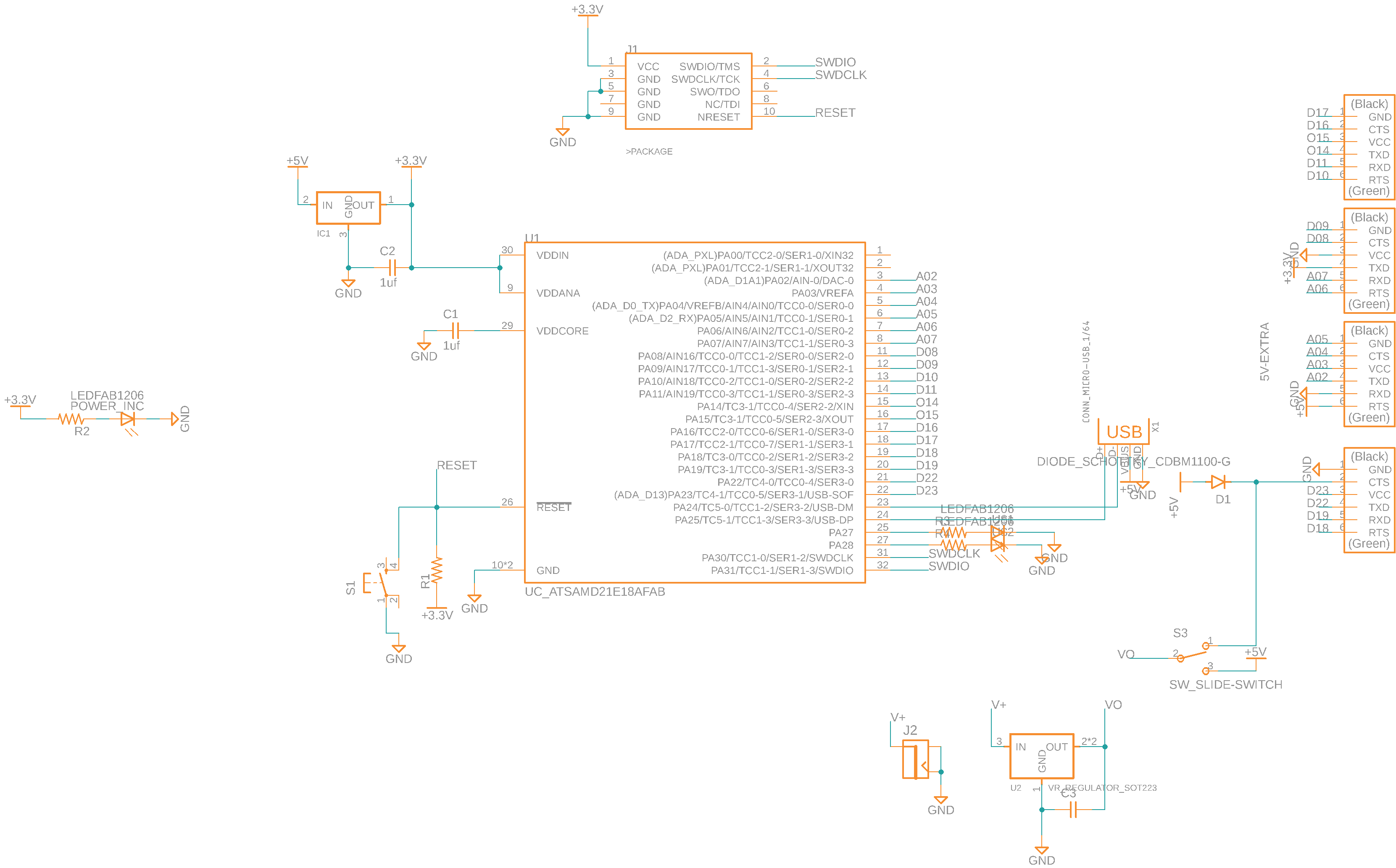 Schematic for dev board
Routing the board
Before I started to route the board I'll admit I was a little scared. My previous boards didn't have nearly as many components. I began by placing the SAMD11E in the centre of the board and connecting it to the FTDI headers. At this stage I realised routes were going to cross. Instead of adding 0 ohm resistor I changed the location of some of the pins in the schematic until everything was attached with no crosses.
After this, I placed the other components and routed them all. In the end I was able to get it all to work without any vias or 0 ohm resistors. The trick was to have a ground trace which went on the other side of the FTDI header pads and to route underneath the SAMD11E and button.
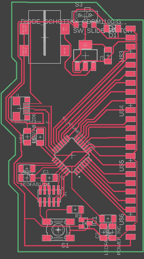 Routed dev board
Adding a little flair
The only thing left was to add a little bit of flair to my board.
During my freshmen when writing some equations on a whiteboard the number 1213 came up. This looks pretty inconspicuous but my handwriting is atrocious so all the numbers were mashed together and it came out looking like RB which conveniently are my initials. Ever since, I've put 1213t on things that I make. However, not just any 1213t, but 1213t written in an obscure font which I found while doing Metropolis' water jet training. I've never been able to find the font again so whenever I want my initials I have to find a saved copy.
 Initals
I had my initials saved as an SVG so initially wanted to import that. Unfortunately, Eagle had incredible poor support for images.
I found a sparkfun guide and followed that. For .svgs it gets you to install a new ULP script. On my Mac I couldn't easily find the location of my ULP script folder, to get yours you can: click your profile in the top right > Preferences > Electronics > Directory and then copy the Directory for ULP.
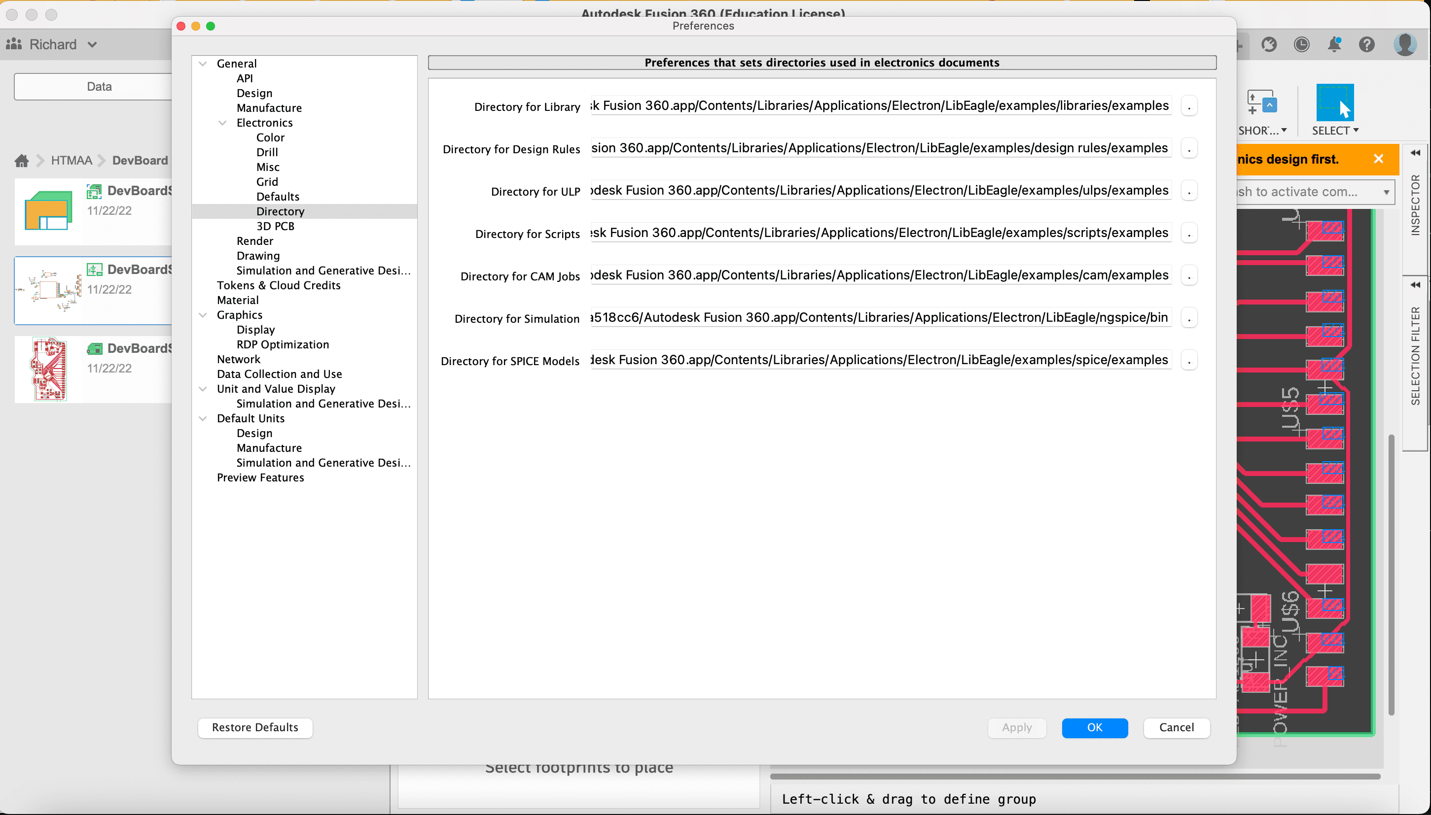 ULP directory in eagle settings
Next I ran the svg2poly script, clicked on my file, and clicked Ok
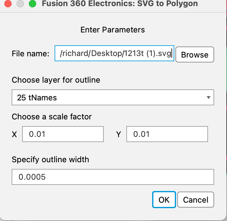 svg2poly prompt
Nothing appeared 😥. I fiddled with the scales, and still got nothing. Ok, well the sparkfun guide had two other options so I decided to try those.
The next one was .dxf but I thought that would be similar to .svg so instead I tried using the bitmap.
I opened up my .svg in Illustrator and exported it for bitmap. Illustrator will then ask for a colour profile. I tried all of them and only bitmap words. To import the bitmap you run run import-bmp and select your file. When I selected a RGB colour profile it complained that there were too many colours and for greyscale Eagle showed off how old of a program it was by displaying the colour selection window so large that I couldn't click the ok or cancel button.
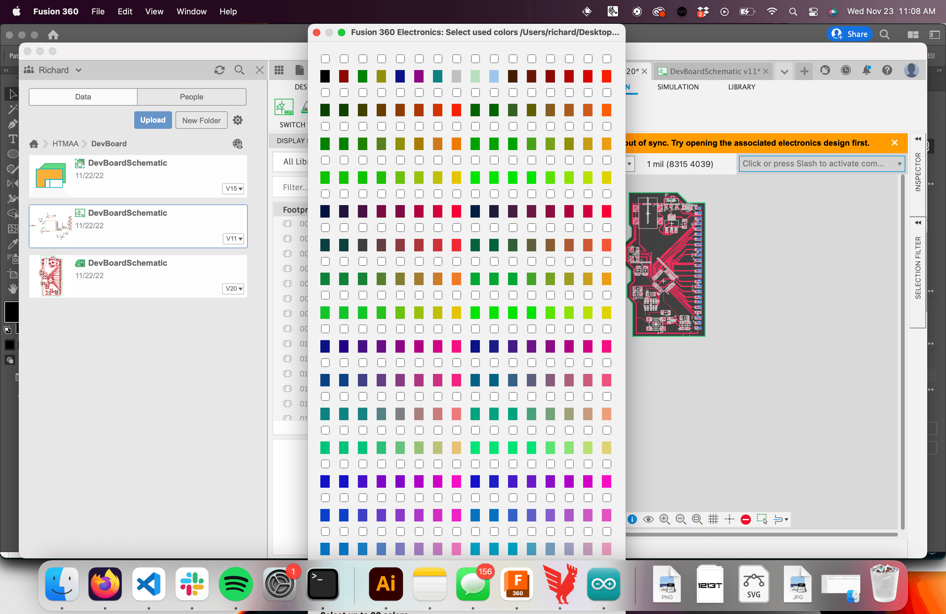 Colours being too large for screen
When using bitmap mode I was able to select black and white and it imported my image! But, it's literally composed of individual squares of a specific colour. When importing the image I skimmed the warning prompt but the TL;DR; was that this feature wasn't intended to make features you'd keep but rather features you'd trace over with the polygon tool.
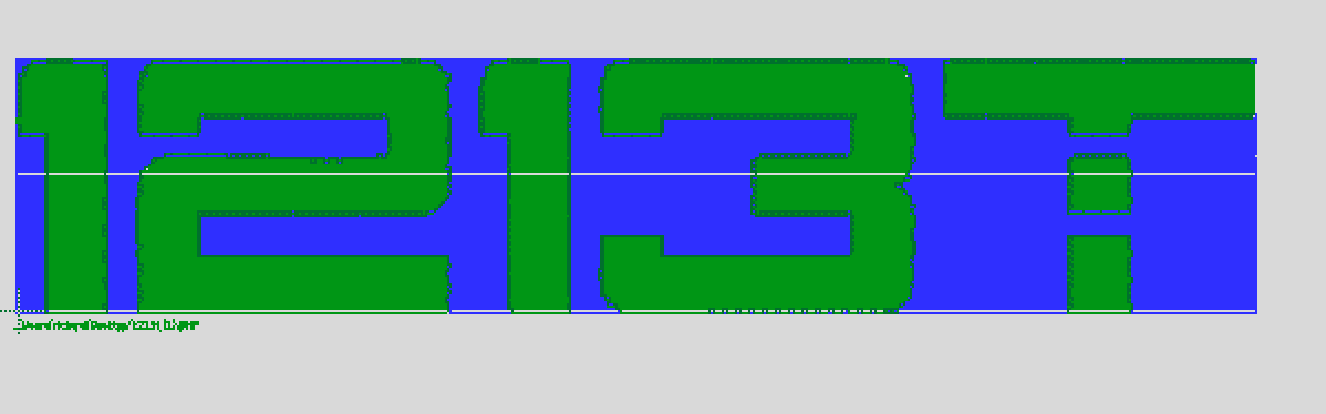 1213t imported as bitmap
The only option left to try was using .dxf files. I went back to Illustrator and reexported my svg as a dxf this time. Then I used the run import-dxf command. This creates a popup which asks for you to select a location and specify a scale. The first time I ran this command it showed me nothing, but after messing around with the scale property I eventually got something visible!
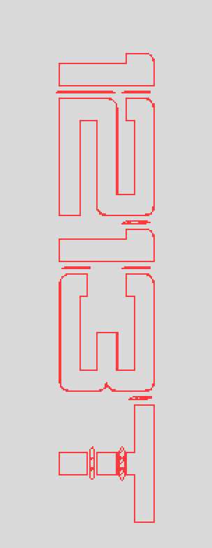 1213t imported as a dxf
Unfortunately, due to my clearance settings the traces were all too close to each other and Eagle wouldn't let me move them directly. I had to deform each letter to make it compliant with the dxf rules, move it individually and reassembled at the end. I then filled in the area surrounded by the letter traces using Polygon > Polygon Pour from Outline. It looked pretty awful.
Then I tested what it would look like in the Othermill.
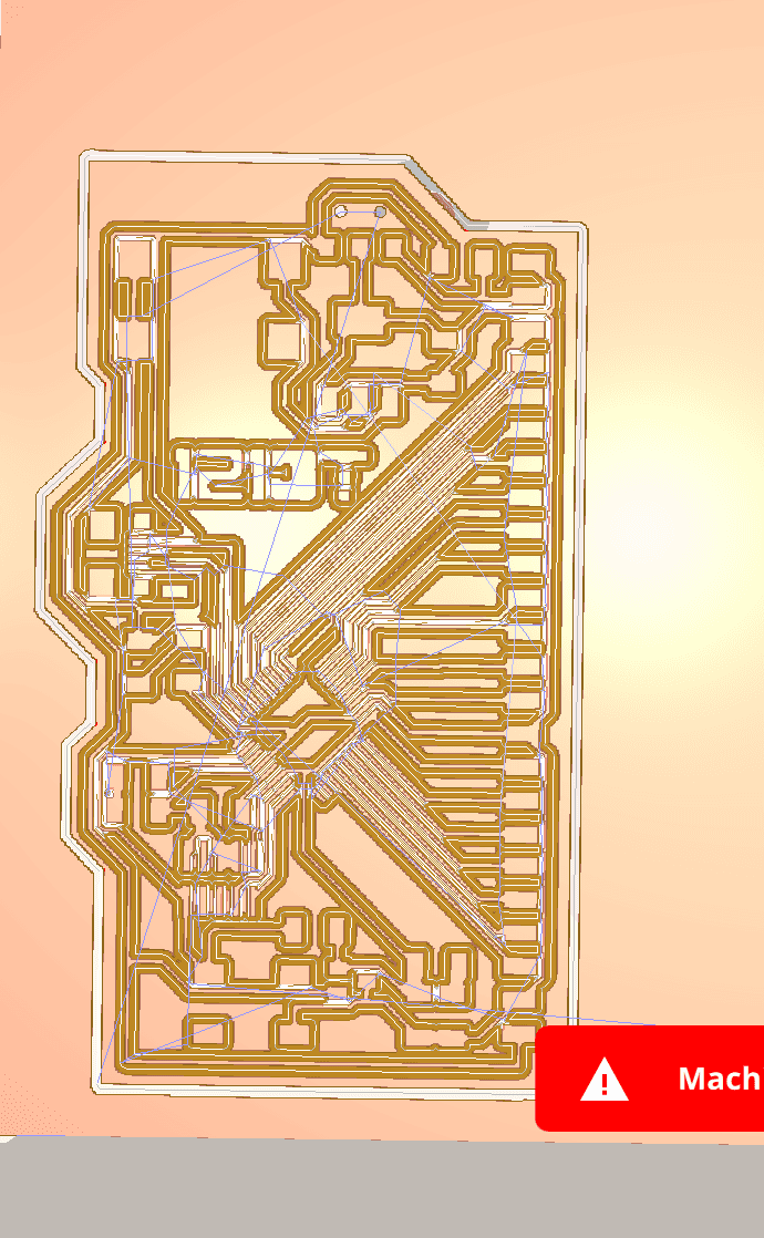 Awful CAM plan for 1213t in OtherMill
Awful! It no longer looked like my signature. At this point I was 2 hours in and pretty frustrated. Finally I did what I should of done at the very beginning and started googling. Eventually I realised that the Othermill supports engraving with svgs directly. Not gonna lie, I was a little bit annoyed. Why couldn't I have realised that 2 hours earlier! See below for how I set this up.
Milling the board
I found some PCB engraving bits which I wanted to try use instead of the 1/64” bit I had been using. The 1/64” cost around $18 and easily break due to how small it is. The engraving bits cost ~$1 and last much longer as they have a lot more metal due to being tapered. Also, they're so much faster. Switching from the 1/64” FEM to 0.005” engraving bit reduced my milling time from 39 to 25 minutes.
 Othermill job time using 1/64 endmill
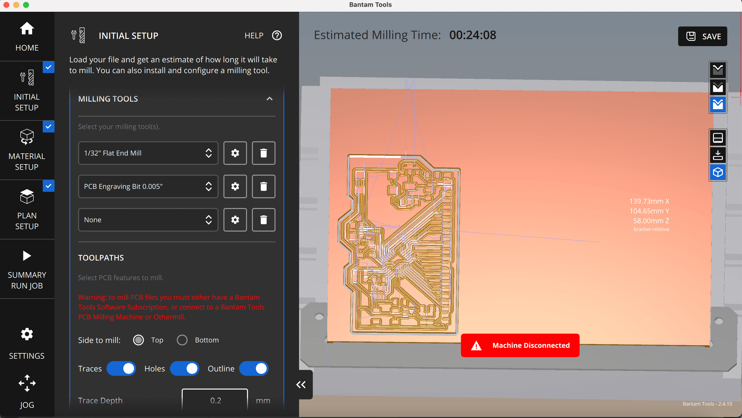 Othermill job time using 0.005 engraving bit
Before starting I found a guide by Bantman Tool's (the company OtherMill rebranded to) about how to properly setup the engraving bit.
I carefully stuck the double sided tape so none of it overlapped (which would cause a height difference). Then I measured the thickness of my material and tape with a digital callipers and inserted it under thickness.
Once everything was set up I added the svg file. With the Bantman tool software this was super easy. Exactly the same as adding a .brd file I clicked Open file, selected my SVG, and then changed the tool it wanted to use to the 0.005” PCB engraving bit. Finally in the Plan setup tab I positioned the text where I wanted it engraved**.
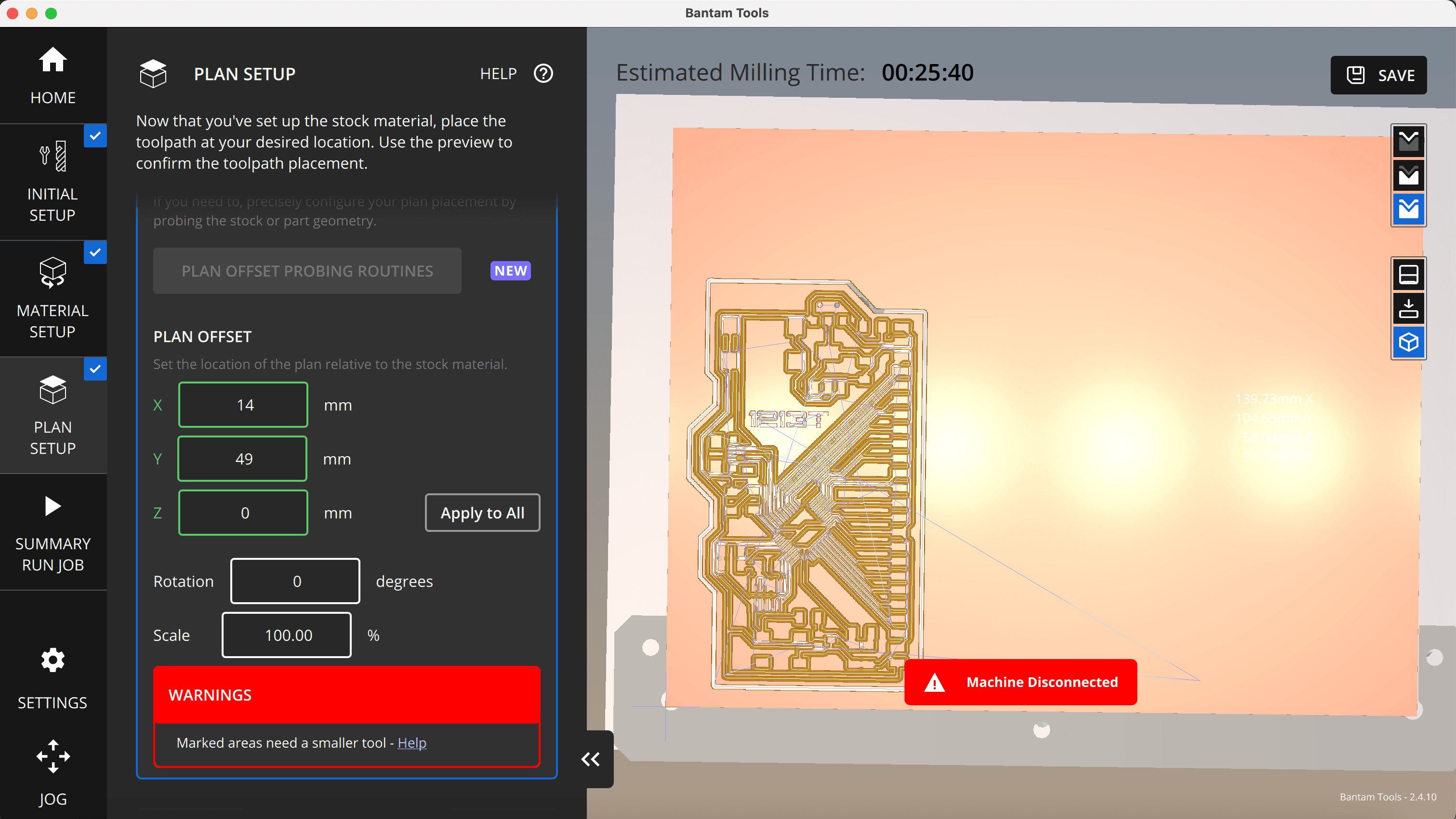 Othermill job
Once setup, I ran the milling job and everything worked great.
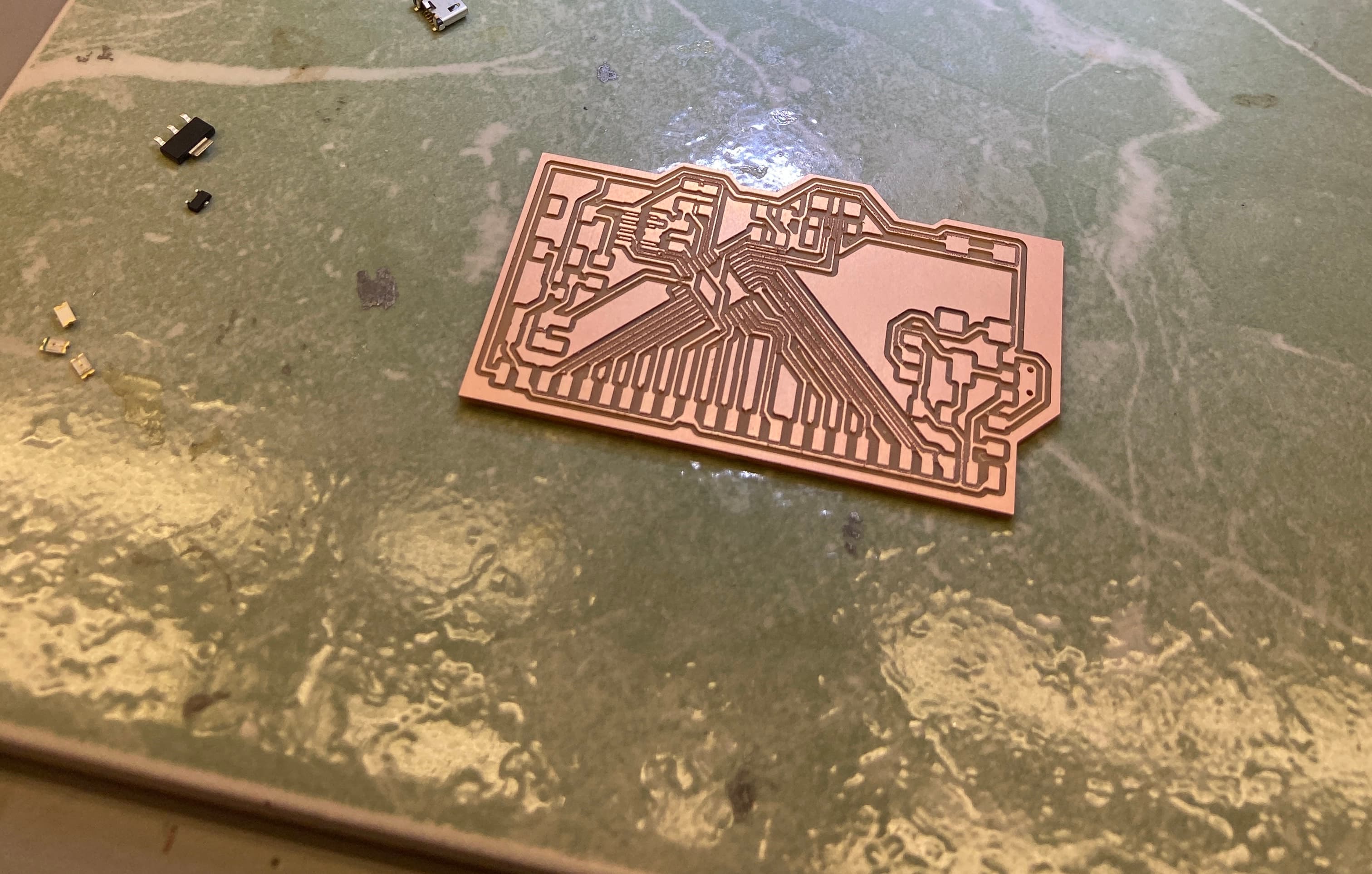 Milled board
Soldering
The SAMD21E is a pretty small chip so I used solder paste and a hot air gun to solder it. I then soldered the rest of the components by hand.
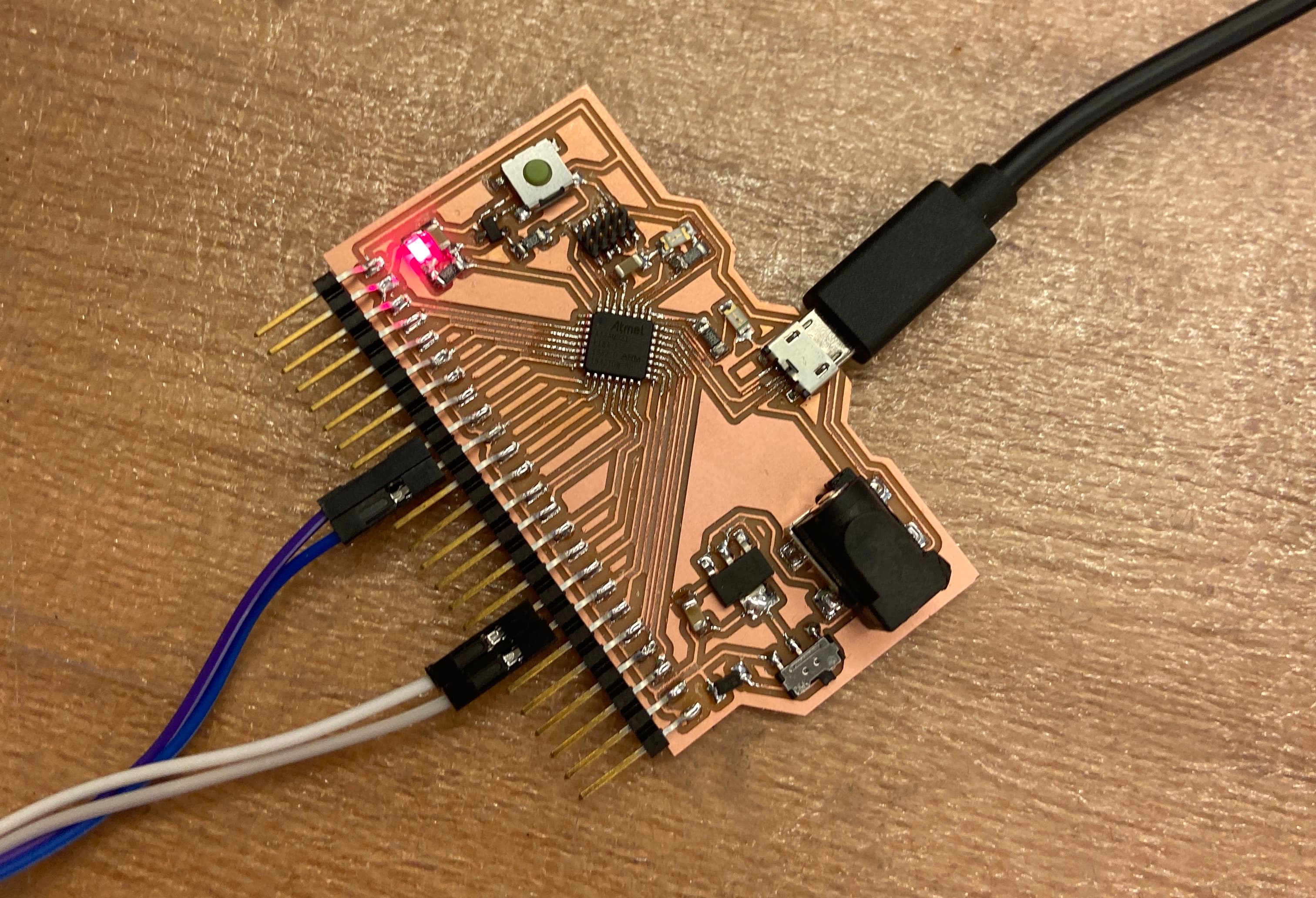 Soldered Dev Board